

Use Ladder Diagram (LD) when technicians need to inspect discrete interlocks as contact-and-coil logic. Use Function Block Diagram (FBD) when the dominant question is how typed values move through functions. Use Sequential Function Chart (SFC) when a machine or batch advances through explicit phases. A production PLC application can—and often should—use more than one.
IEC 61131-3:2025 describes a unified suite containing Structured Text plus the graphical LD and FBD languages; it also defines SFC graphical and textual elements for organizing programs and function blocks. That distinction matters: these are complementary representations, not competing skins over the same graph.
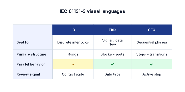
The practical crosswalk
| Question | Ladder Diagram | Function Block Diagram | Sequential Function Chart |
|---|---|---|---|
| Dominant mental model | Energized path through contacts | Values moving through functions | Active step and allowed transition |
| Strongest fit | Discrete machines, permissives, interlocks | Analog processing, reusable functions, control calculations | Batch phases, recipes, robot cells, coordinated sequences |
| Review unit | One rung | One signal path or network | One step-transition chain |
| Parallel behavior | Parallel branches inside a rung | Independent block networks | Explicit simultaneous branches and convergence |
| Most common readability failure | Dense rung with hidden side effects | “Spaghetti” wiring and implicit types | Giant chart that tries to contain every low-level action |
| Poor reason to choose it | “Electricians like it” without checking the task | “It looks modern” | “The system has states” |
The last row prevents three recurring category errors. A stateful system does not automatically need SFC. A function block does not automatically make analog control readable. And familiar ladder notation does not rescue a rung that mixes sequencing, diagnostics, mode management, and output actuation.
Choose LD when the review question is “what permits this output?”
LD exposes a Boolean path. A reviewer can follow normally open and normally closed contacts, branches, timers, and coils to determine why an output is or is not energized. This makes it strong for motor starts, permissive chains, safety-adjacent interlocks, and maintenance diagnostics.
The useful boundary is not “simple versus complex.” LD can express complex behavior. The boundary is whether the contact-and-coil representation keeps the cause of an output legible. When a rung becomes a compressed state machine, its visual familiarity begins to hide rather than reveal behavior.
Schematex treats LD contacts and coils as typed PLC elements rather than generic rectangles. See the Ladder Diagram syntax reference for the exact supported instruction vocabulary.
Choose FBD when the review question is “where did this value come from?”
FBD is strongest when named inputs flow through timers, counters, comparisons, arithmetic, selectors, and reusable function blocks. Port names and data types carry meaning that would otherwise be buried in expressions or repeated contacts.
A bottle counter is a good example: a rising-edge detector feeds a counter; the counter’s current value and done output feed downstream logic. The diagram’s job is to make data dependencies inspectable. If the same logic is rendered as a ladder rung, the scan behavior may still be correct, but the transformation pipeline is harder to see.
The failure mode is uncontrolled wiring. Split FBD into networks with one clear responsibility, name intermediate values, and do not route every signal across the entire sheet. The FBD reference documents the standard blocks and port conventions Schematex renders.
Choose SFC when the review question is “which phase is active, and what can happen next?”
SFC makes phase ownership explicit. Steps become active; transitions permit movement; alternative branches choose one path; simultaneous branches activate multiple paths and wait for convergence. It is therefore a strong fit for fill–heat–hold–drain recipes, robot handshakes, packaging cells, and other processes where sequence is the primary structure.
SFC should orchestrate rather than absorb the entire controller. A step action can call a function block or enable ladder logic. Keeping device-level permissives outside the sequence prevents a chart from becoming an unreviewable wall of actions.
The SFC reference distinguishes alternative and simultaneous branches, step actions, qualifiers, and transitions.
A mixed-language architecture is often clearer
Consider a batch oven:
- SFC owns
Idle → Heat → Soak → Cool → Complete. - FBD owns temperature scaling, PID-related signal conditioning, and timer/counter networks.
- LD owns hard-to-miss fan, door, and heater permissives.
This split creates three review surfaces: operations can verify the sequence, controls engineers can trace values, and maintenance technicians can inspect output permissives. The implementation remains one controller application; the views are separated by the question each reviewer needs answered.
What changed in the 2025 edition—and what this page does not claim
The IEC’s public summary says Edition 4 adds UTF-8 strings and provides a comprehensive list of features added, removed, or deprecated relative to the 2013 edition. The complete normative detail is paywalled. This article therefore makes a narrower claim: it uses the 2025 publication’s public scope to classify LD, FBD, and SFC, while Schematex’s renderer documents its supported subset separately.
That supported-subset statement is important. A diagram library can follow a notation without being a PLC compiler, simulator, functional-safety tool, or substitute for vendor verification. Schematex renders and validates diagram structure; it does not execute the controller scan.
If the goal is to draft one of these diagrams directly from a prose control narrative, ChatDiagram provides the natural-language layer. The resulting diagram still needs engineering review against the actual PLC platform and project standard.