

In a single-line diagram, an automatic transfer switch (ATS) should sit at the convergence of a normal source and an emergency or alternate source, with one switched output feeding the downstream bus or load. Label the equipment function and ratings; do not rely on an unlabeled switch glyph to communicate transfer logic.
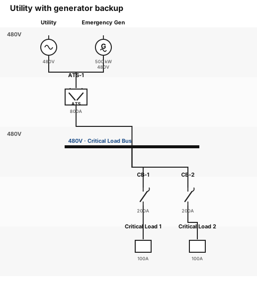
Read the chain from source to load
The worked diagram contains seven functional stages:
- Utility — the normal source, labeled
480V. - Emergency generator — the alternate source, labeled
500 kW / 480V. - ATS-1 — the source-selection point, labeled
800A. - Critical Load Bus — the common downstream distribution point.
- CB-1 and CB-2 — branch protective devices.
- Critical Load 1 and 2 — the supplied loads.
The topological statement is more important than the icon: two mutually considered source paths enter the ATS, and one path leaves it. Drawing two sources directly onto the same bus without an explicit transfer or paralleling device would communicate a materially different system.
Symbol, label, and function number are different things
IEEE/ANSI 315 is a graphic-symbol reference. IEEE C37.2 covers device function numbers, acronyms, and contact designations used in power systems. These sources answer different questions:
| Layer | Question answered | Example in the diagram |
|---|---|---|
| Graphic symbol | What kind of equipment is shown? | Generator, transfer switch, breaker, bus |
| Equipment tag | Which physical or logical item is it? | ATS-1, CB-1 |
| Rating | What declared operating envelope is relevant? | 480V, 800A, 500 kW |
| Device function | What protection/control function is referenced? | C37.2 function numbers where the project uses them |
Do not invent a C37.2 number merely because a device appears on the SLD. A breaker symbol, an equipment identifier, and the protection functions acting on that breaker belong to related but distinct notation layers.
Minimal reproducible source
sld "Utility with generator backup"
UTIL = utility [voltage: "480V", label: "Utility"]
GEN = generator [rating: "500 kW", voltage: "480V", label: "Emergency Gen"]
ATS1 = ats [rating: "800A", label: "ATS-1"]
BUS1 = bus [voltage: "480V", label: "Critical Load Bus"]

UTIL -> ATS1
GEN -> ATS1
ATS1 -> BUS1
Additional breakers and loads extend the downstream tree without changing the transfer topology. The complete rendering above adds two protected branches.
What a useful ATS one-line should make explicit
- Normal and alternate sources are visually distinct.
- Nominal voltages are compatible or the required transformation is shown.
- The transfer device is named, not inferred from crossing lines.
- The switched output has one clear downstream destination.
- The ATS continuous-current rating is visible where it matters to review.
- Generator capacity and load naming are present at the appropriate level.
- Protective devices are not confused with the transfer mechanism.
What the diagram intentionally does not prove
This figure does not determine whether the ATS is open-transition, closed-transition, delayed-transition, bypass-isolation, service-rated, or suitable for the application. It does not show neutral switching, grounding and bonding, selective coordination, conductor sizing, available fault current, generator start logic, or jurisdiction-specific emergency-system requirements.
Those omissions are not defects in a topology reference. They become defects only if someone treats the reference as an issued design.
Common diagram errors
Both sources appear continuously tied
If utility and generator land on the same bus with no transfer/paralleling element, the diagram suggests simultaneous connection. Add the ATS explicitly or model the actual paralleling switchgear.
The ATS is present but its inputs are ambiguous
Crossed connectors or unlabeled terminals make it unclear which source is normal. Preserve one connector per source and label the equipment or port convention used by the project.
Ratings are attached to the wrong object
Generator kW, bus voltage, ATS current, and breaker trip/frame information answer different review questions. Keep each rating with the equipment it describes.
The Schematex SLD reference documents the supported equipment vocabulary and deterministic power-flow layout. For a no-code draft from a system description, CircuitMaker provides a focused natural-language interface; the result still requires qualified electrical review.