

For 18 staff endpoints and 10 cameras, allocate 192.168.10.0/27 to staff and 192.168.10.32/28 to cameras. The /27 supplies 30 traditional usable host addresses, leaving 11 after 18 endpoints and one gateway; the /28 supplies 14, leaving 3 after 10 cameras and one gateway. Map the two prefixes to VLAN 10 and VLAN 20, but review them as separate facts: a VLAN is a Layer 2 broadcast domain, while a subnet is a Layer 3 address prefix.
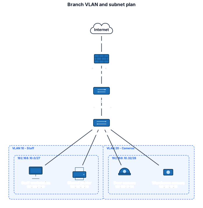
Scope: a design worksheet, not switch configuration
This worked example turns a small inventory into an auditable logical topology. It checks prefix capacity, non-overlap, sample host membership, VLAN labels, and the path from endpoints to the routed core. It does not generate vendor CLI, assign DHCP scopes, define firewall rules, prove isolation, calculate PoE load, or establish that the physical cabling can carry the labeled speeds.
The terms are easy to blur because many enterprise designs map one IPv4 subnet to one VLAN. IEEE 802.1Q defines the bridged-network and VLAN mechanisms; RFC 4632 defines IPv4 prefix notation. They do not make “VLAN” and “subnet” synonyms. NIST SP 800-215 describes a common segment-based design in which resources with similar security requirements are grouped using VLAN IDs and policies are expressed using network addresses and ports. That mapping is a design choice that must remain explicit.
This fictional branch has one perimeter firewall, one Layer 3 core, and one access switch. The core is assumed to route between the two VLAN interfaces. Whether inter-VLAN traffic is filtered on that core, sent through the firewall, or denied elsewhere is deliberately outside the diagram.
Inputs and assumptions
| Input | Staff network | Camera network |
|---|---|---|
| Planned endpoints | 18 | 10 |
| Reserved default gateway | 1 | 1 |
| Required host addresses | 19 | 11 |
| VLAN ID | 10 | 20 |
| Candidate prefix | 192.168.10.0/27 | 192.168.10.32/28 |
| Sample device addresses | .10, .20 | .34, .35 |
The parent block 192.168.10.0/24 is within the private-use range that RFC 1918 reserves for private internets. Private does not mean trusted, encrypted, or unreachable from the Internet; it only describes address use. Network address translation, routing, filtering, and exposure remain separate design decisions.
The capacity calculation uses conventional multiaccess IPv4 subnets: the all-zero host number is the subnet address and the all-one host number is the directed broadcast address. Special cases such as a /31 point-to-point link are not part of this example.
Calculate the /27 staff range
IPv4 has 32 bits. A /27 fixes 27 prefix bits and leaves 32 - 27 = 5 host bits:
addresses in /27 = 2^(32 - 27)
                 = 2^5
                 = 32 addresses

traditional usable hosts = 32 - 2
                         = 30 hosts

planned use = 18 endpoints + 1 gateway
            = 19 hosts

spare capacity = 30 - 19
               = 11 hosts
RFC 4632's prefix table gives 32 addresses for a /27. Because the block size is 32, the subnet beginning at 192.168.10.0 ends at .31:
| Role | Address |
|---|---|
| Subnet address | 192.168.10.0 |
| First traditional usable host / assumed gateway | 192.168.10.1 |
| Last traditional usable host | 192.168.10.30 |
| Broadcast address | 192.168.10.31 |
The sample staff workstation .10 and printer .20 both fall between .1 and .30. Neither is the subnet nor broadcast address.
Calculate the /28 camera range
A /28 leaves four host bits, so the block size is 16. The next aligned block after the staff /27 starts at .32:
addresses in /28 = 2^(32 - 28)
                 = 2^4
                 = 16 addresses

traditional usable hosts = 16 - 2
                         = 14 hosts

planned use = 10 cameras + 1 gateway
            = 11 hosts

spare capacity = 14 - 11
= 3 hosts| Role | Address |
|---|---|
| Subnet address | 192.168.10.32 |
| First traditional usable host / assumed gateway | 192.168.10.33 |
| Last traditional usable host | 192.168.10.46 |
| Broadcast address | 192.168.10.47 |
The camera samples .34 and .35 are valid host addresses. The two prefixes cannot overlap: the staff interval ends at .31, and the camera interval begins at .32. The next unallocated address is .48; do not call 192.168.10.48/28 usable space until a third requirement and route policy have actually been approved.
Reproducible Schematex source
network "Branch VLAN and subnet plan"
  layout: manual
  internet inet "Internet" at: 326,40
  firewall fw1 "Perimeter firewall" tier: edge at: 326,150
  l3switch core1 "Layer 3 core" tier: core at: 326,260
  switch acc1 "Access switch" tier: access at: 326,370
  vlan staffv "10 - Staff" {
    subnet staff "192.168.10.0/27" {
      pc staff1 "Staff workstation" ip: 192.168.10.10 at: 100,540
      printer prn1 "Shared printer" ip: 192.168.10.20 at: 250,540
    }
  }
  vlan iotv "20 - Cameras" {
    subnet iot "192.168.10.32/28" {
      camera cam1 "Door camera" type: dome ip: 192.168.10.34 at: 405,540
      camera cam2 "Warehouse camera" type: fixed ip: 192.168.10.35 at: 555,540
    }
  }
  inet -- fw1 : 1G
  fw1 -- core1 : 10G
  core1 -- acc1 : trunk vlan: 10,20 10G
  acc1 -- staff1
  acc1 -- prn1
  acc1 -- cam1
  acc1 -- cam2
This source was strictly validated and rendered with Schematex 1.0.10 on August 20, 2026. Validation returned no errors or warnings, and the SVG reports 8 devices, 7 links, and 4 boundaries in the manually positioned topology. The current network topology syntax reference documents nested VLAN/subnet boundaries, CIDR membership checks, trunk and access annotations, VLAN IDs, device kinds, and link types. That owned documentation establishes renderer behavior; the external references establish the networking concepts.
Only representative endpoints are drawn. The inventory totals drive the capacity calculation, but drawing all 28 endpoints would make the figure worse at its job: reviewing boundaries and paths. The prose and table therefore remain part of the controlled design record.
Invariants to check before approval
- Capacity covers the inventory and gateway.
30 ≥ 19for staff and14 ≥ 11for cameras. Record whether DHCP reservations, high-availability addresses, network appliances, and growth need additional slots. - Every prefix is aligned. A /27 inside this /24 starts on a multiple of 32; a /28 starts on a multiple of 16.
.0/27and.32/28satisfy those boundaries. - The address intervals do not overlap. Staff occupies
.0–.31; cameras occupy.32–.47. - Every shown IP belongs to its declared subnet. Moving
cam1from.34to.20must fail the Schematex membership check because.20belongs to the staff /27. - Every representative endpoint belongs to one logical boundary in this model. Staff devices are nested under VLAN 10 and cameras under VLAN 20. Reconcile that intent with actual access-port configuration; the boundary does not configure the switch.
- The uplink carries every required VLAN. The core-to-access trunk lists both 10 and 20. A VLAN used by an endpoint boundary but absent from the trunk is disconnected from the stated routed path.
- Layer 2 separation is not credited as a firewall rule. The diagram shows segmentation, not permitted traffic. Document DNS, DHCP, NTP, camera-management, recording, administration, and Internet flows in a separate policy matrix.
- The physical design reconciles. Confirm switch port count, link speed, redundancy, transceiver/media type, PoE class and budget, cable routes, equipment ownership, and monitoring against the actual bill of materials.
Failure modes the clean diagram can hide
A VLAN-only security claim. NIST SP 800-41 Rev. 1 places firewalls at logical boundaries where security requirements differ. A VLAN boundary alone does not say which device inspects or denies traffic. NIST SP 800-215 also warns that segment-based policy depends on keeping application requirements, network locations, VLANs, addresses, and rules synchronized as systems change.
A one-to-one mapping that exists only on paper. An endpoint can be assigned to the wrong access VLAN, a trunk can omit a VLAN, or a Layer 3 interface can use the wrong prefix. Validate running configuration and forwarding behavior; do not infer them from a drafted topology.
Capacity with no operational reserve. Three spare camera addresses may be numerically valid yet operationally poor if the design later adds an NVR, time server, redundant gateway, maintenance laptop, or additional cameras. The correct reserve comes from an owned inventory and growth assumption, not an arbitrary percentage.
Unshown failure paths. One firewall, core, access switch, and uplink are single points of failure in this drawing. Adding duplicate icons is not a redundancy analysis: power, control plane, LAG behavior, spanning-tree or multi-chassis design, state synchronization, and failure testing all need explicit treatment.
Paste the source into the Schematex playground, first changing cam1 to 192.168.10.20 to confirm the out-of-subnet error. Restore .34, then remove VLAN 20 from the trunk and use the checklist to catch the resulting design inconsistency that syntax validation alone cannot prove. Finally, replace the fictional counts with an owned device inventory and record the person who approves each address, VLAN, route, and policy boundary.